Antennas: Principles, Performance Parameters, and Classification
1、 The function of the antenna
The antenna emits and receives radio waves. However, the transmitter that passes through the feed line to the antenna is not a radio wave. The receiving antenna cannot directly transmit radio waves to the receiver through the feed line, and the receiver must undergo an energy conversion process. Here, we analyzed the signal transmission process using wireless communication equipment as an example, and then explained the role of antenna energy conversion.

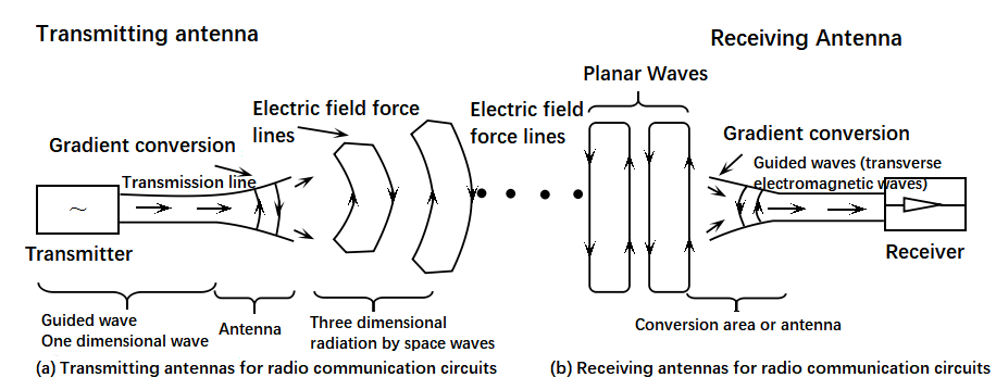
Schematic diagram of antenna energy conversion
On the transmitter side, the transmitter has modulated high-frequency oscillation current (energy) into the transmission antenna through a feed line. The transmitting antenna converts high-frequency current or guided waves (energy) into radio waves - free electromagnetic waves (energy, radiating into the surrounding space) (see figure); At the receiving end, radio waves (energy) are converted into high-frequency current through the receiving antenna or guided waves (energy) guided by the feeding device to the receiver. From the above process, it can be seen that antennas are not only devices for transmitting and receiving radio waves, but also energy converters are interface devices between circuits and space.
2、 Antenna principle
The principle of antennas should be divided into two parts, one is the transmitting antenna, and the other is the receiving antenna. Transmission antenna: Through the electrodes between the antenna and the ground, high-frequency electric fields are formed into electromagnetic waves, which can be emitted and sent to a distance. Receiving antenna: Electromagnetic waves from the air are induced by electrodes to form an electric field, generating high-frequency signal voltage that is sent to the receiver for signal processing.
3、 Antenna performance parameters
1 Operating frequency range
Frequency range: Whether it is an antenna or other communication product, it always operates within a certain frequency range (bandwidth), depending on the requirements of the indicator. Usually, the target requirement for the frequency range can be the operating frequency of the antenna. The working band width is called the working band width. Generally, the working band width of the omnidirectional antenna can reach 3-5% of the center frequency, and the working band width of the directional antenna can reach 5-10% of the center frequency band.
2 input impedance
Input impedance: The ratio of antenna input signal voltage to signal current, known as antenna input impedance. The input impedance of a general mobile communication antenna is 50 Ω. The input impedance is related to the structure, size, and operating wavelength of the antenna. Within the required operating frequency range, the input impedance of the imaginary part is very small, while the real part is very close to 50 Ω, which means that the antenna and feeder have good impedance matching.
3 Voltage Standing Wave Ratio (VSWR)
The standing wave ratio, also known as the voltage standing wave ratio, refers to the ratio of the voltage at the standing wave belly to the amplitude of the valley voltage, also known as the standing wave coefficient or the standing wave ratio. When VSWR is equal to 1, the impedance of the feeder and antenna perfectly match. At this point, all high-frequency energy is radiated by the antenna without any reflected energy loss. When the standing wave ratio is infinite, i.e. total reflection, energy will not be completely radiated.
VSWR is formed by the iterative generation of reflected waves, as the energy of the incident wave is not fully absorbed (radiated) when transmitted to the antenna input. The higher the standing wave ratio, the greater the reflection, and the worse the matching. In mobile communication systems, the general requirement for standing wave ratio is less than 1.5.
4 Isolation
The isolation degree represents the proportion of signals fed into one port (one polarization) of a dual polarization antenna to signals in another port (another polarization).
5th order intermodulation
Third order intermodulation signal: there are two signals in the linear system. Due to the presence of nonlinear factors, the second harmonic of one signal and the fundamental of another signal generate differential beat frequency (mixing) after the parasitic signal. Intermodulation phenomenon refers to the phenomenon where two or more carrier frequencies from outside the frequency band mix after falling into the frequency band of a new frequency component, resulting in a decrease in system performance.
6 power capacity
Power capacity: The power capacity of an antenna refers to the maximum continuous RF power that can be continuously applied to the antenna within a specified time period, under specified conditions, without reducing the performance of the antenna.
7 gain
Antenna gain is used to measure the ability of an antenna to send and receive signals in a specific direction, and is one of the important parameters for selecting a base station antenna. The higher the antenna gain, the better the directionality, the more concentrated the energy, and the narrower the flaps.
Width of 8 H/V plane half power beam
In the main lobe of the power pattern, the relative maximum radiation direction power drops to half or less of the maximum 3dB beamwidth angle between two points, which is called half power beamwidth. The horizontal plane of half power beam width is called horizontal beam width; The vertical plane of the half power beamwidth is called the vertical beamwidth.
9 Electrical tilt down
The downward inclination angle is the maximum vertical radiation directed towards the communication antenna, and the antenna angle is normal. Communication antennas are divided into fixed tilt down antennas and electric tilt down antennas based on whether they support electric tilt down adjustment. Fixed tilt down refers to the fixed tilt down generated by the amplitude and phase distribution of the antenna radiation unit array according to wireless coverage requirements. Electric tilt antenna refers to the phase difference generated by different radiation units in an array through phase shifting units in the downward tilt state of the main flap. Usually, the lower state of electrically tuned antennas is only within a certain adjustable angle range.
10 Cross polarization rat
In the 3dB beamwidth of the directional pattern, the difference between the power level of the antenna with polarized reception (maximum reception level) and the power level of heteropolar reception (minimum reception level).
11 Circle
The roundness of the omnidirectional antenna pattern is the deviation between the maximum or minimum horizontal value and the average value in the horizontal pattern. The average value is the arithmetic mean value of the maximum interval of the horizontal dB value not exceeding 5 ° in the horizontal pattern.
12 polarization
The direction of the electromagnetic field radiated by the antenna is the polarization direction of the antenna. If the direction of the electric field is perpendicular to the ground, we call it vertical polarization; If the direction of the electric field is parallel to the ground, it is called horizontal polarization; If the direction of the electric field is at a 45 ° angle to the ground, it is called+45 ° or -45 ° polarization.
4、 Antenna classification
1 Mechanical antenna
The so-called mechanical antenna refers to a mobile antenna that uses mechanical adjustment at a downward angle. After the installation of the mechanical antenna, if it meets the requirements of network optimization, it is necessary to adjust the position of the rear bracket of the antenna to change the tilt angle of the antenna. During the adjustment process, although the coverage distance of the main lobe direction of the antenna has significantly changed, the amplitude of the vertical and horizontal components of the antenna remains unchanged, making the antenna pattern prone to deformation.
Practice has proven that the optimal inclination angle for mechanical antennas is 1-5 degrees; When the inclination angle changes within the range of 5-10 degrees, the antenna pattern does not change much; When the tilt angle changes between 10-15 degrees, the antenna pattern changes more significantly; When the mechanical antenna tilts more than 15 degrees, the shape of the antenna pattern will undergo significant changes. Adjusting the inclination angle of mechanical antennas is very troublesome, and maintenance personnel usually need to climb to the antenna installation site to make adjustments.
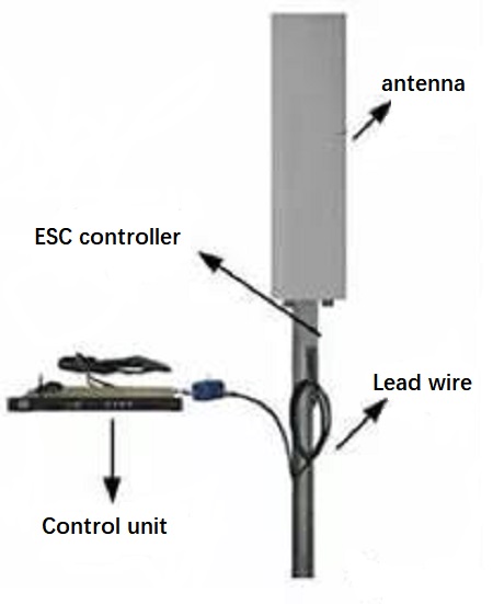
2 Electrical tuning antenna

Electrically tuned antenna
The so-called electrically tuned antenna is a mobile antenna that uses electronic devices to adjust the downward tilt angle. The principle of electronic tilt is to tilt the antenna in the vertical direction by changing the phase of antenna array antenna oscillator, changing the size of vertical component and horizontal component, and changing the field strength of composite component. Due to the simultaneous increase and decrease of antenna field strength in each direction, it is ensured that the antenna pattern will not change too much after changing the inclination angle, thereby shortening the coverage distance in the main flap direction. At the same time, the entire pattern is made in the service community sector to reduce the coverage area but not generate interference.
3 omnidirectional antenna
The omnidirectional antenna has a uniform radiation pattern in the horizontal direction. However, from a vertical perspective, the radiation pattern is concentrated, so antenna gain can be obtained. Arranging the dipoles on the same vertical line and feeding the correct power and phase to each dipole unit can increase the radiation power. For every doubling of the number of dipole units (equivalent to twice the length), the gain increases by 3dB. The typical gain is 6-9 dBd. The main factor that is limited by factors is physical size. For example, a omnidirectional antenna with a gain of 9 dBd has a height of 3 meters.
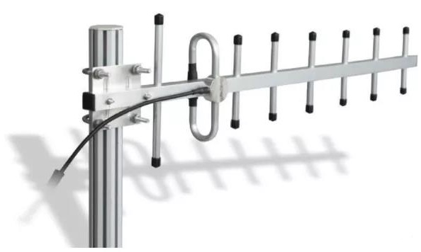
4 directional antenna

Directional antenna
The horizontal and vertical radiation patterns of this type of antenna are uneven. It is often used for fan-shaped cells. Therefore, it is also known as a sector antenna. The radiation power is more or less concentrated in one direction. The typical value of directional antenna is 9~16dBd.
-
Whatsapp

