What is an RF filter?
In RF/microwave systems, it is usually necessary to distinguish between useful and useless frequency signals in the signal spectrum. A filter is a device that achieves this goal.
Filter is an important RF component in wireless communication systems.
Filter out image frequency interference, reduce noise, and use frequency division multiplexing.
Oscillation, amplification, doubling, and mixing circuits with excellent performance
Within the passband range, RF/microwave filters refer to filters in the RF and microwave frequency bands. One of the most important components in consumer electronics is the RF filter, which is usually called "RF interference filter". A radio frequency filter is a filter circuit composed of capacitors, inductors, and resistors, used to filter the signal frequency in a communication channel. The filter allows signals that meet a specific frequency to pass through while suppressing unwanted frequency signals. It is widely used in radio frequency signal processing systems of base stations and terminal devices to solve the problem of signal interference between different frequency bands and communication systems. From the layout of the RF signal processing system, the filter is located on the back of the power amplifier in the RF transmission path and on the front of the low noise amplifier in the RF reception path.
Networks and coupling structures for effective broadband impedance matching
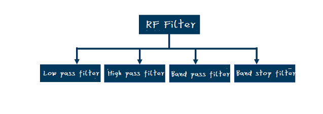
Classification of Two RF Filters
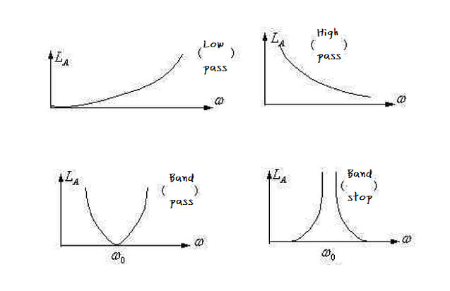
The working attenuation LA is usually used to describe the amplitude characteristics of filters.
Based on attenuation characteristics

Due to low-pass filters, low-frequency signals can be sent from the input port to the output port with a small amount of attenuation. When the signal frequency exceeds the characteristic cutoff frequency, the signal attenuation significantly increases, resulting in a decrease in the signal amplitude at the output port.
High pass filters have completely opposite characteristics. When the signal frequency exceeds a specific cutoff frequency, the signal is attenuated and sent from the input port to the output port.

Specific low and high frequencies separate bandpass filters and bandstop filters into the frequency band. Compared to other frequency bands, the signal attenuators in this frequency band have low (bandpass) or high (bandstop) attenuation.
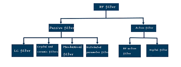
Based on structure

Tuned electronic devices are used for active filters. The wave device is designed to have a specific frequency dependent transmission response, mainly used to suppress unnecessary signal components, interference, or noise in the spectrum.
Resistors, capacitors, inductors, resonators, attenuators, and other passive structures and components form passive filters.
Digital hardware, such as specialized integrated circuits (ASICs), field programmable gate arrays (FPGAs), or digital signal processors, is used to perform signal conditioning functions on digital signals in radio frequency digital filters (DSPs).
Low pass and bandpass filters are the most commonly used filters.
Low pass filters are commonly used for image suppression in mixers and harmonic suppression in frequency sources.
The selection of front-end signals for receivers, the suppression of spurious signals after transmitter power amplifiers, and the suppression of frequency source spurious signals all require bandpass filters.
Technical specifications of three RF filters
Order (Series Quantity
The order of high-pass and low-pass filters is equal to the sum of their capacitors and inductors. The order of a bandpass filter is the total number of parallel resonators, while the order of a bandstop filter is the total number of series and parallel resonators.
Absolute bandwidth/relative bandwidt
This indicator is typically used for bandpass filters to characterize the frequency range of signals that can pass through the filter and represent the frequency selection of the filter. The relative bandwidth relative to the center frequency is expressed as the proportion of absolute bandwidth.
cut-off frequency
Usually high pass and low pass filters are used. The cutoff frequency represents the highest frequency range that a low-pass filter can pass through, while the cutoff frequency represents the lowest frequency range that a high-pass filter can pass through.
standing wave
That is to say, the S11 value determined by the vector network represents the degree of matching between the filter port impedance and the required impedance of the system. The percentage of input signals that have not passed the filter and are reflected back to the input.
Out of band suppression
There is "attenuation" outside the passband frequency range of the filter. Describe the extent to which filters can choose unwanted frequencies
Ripple
The difference between the peak and valley of the S21 curve in the filter passband.
lose
Indicates the energy lost when the signal passes through the filter, or the energy consumed by the filter.
Flatness of passband
The absolute value of the difference between the maximum and minimum losses within the passband of the filter. Filters are used to characterize the energy consumption differences of signals with different frequencies.
Phase linearity
The phase difference between a transmission line with the same time delay as the center frequency and the phase within the passband frequency range of the filter. Determine the dispersed property of the filter.
Absolute group delay
The time required for the signal to be transmitted from the input port to the output port within the passband of the filter.
Power capaci
The maximum power of the passband signal that can be input into the filter.
Phase consistency
The phase difference between different filters in the same index and batch during signal transmission. Determine the differences (consistency) between batch filters.
Amplitude consistency
The difference in signal transmission loss between different filters in the same index and batch. Determine the differences (consistency) between batch filters.
working temperature
The operating temperature range of the filter design.
Application of Four RF Filters
Radio frequency filter is a unique technology that can achieve frequency band filtering. It can achieve filtering, coexistence, duplex, aggregation, and other RF signal functions by selecting frequency components in the signal while significantly attenuating or suppressing other frequency components.
From an application perspective, it can be divided into two categories: "civilian" and "military"
Filters are widely used in the fields of mobile phones, tablets, smart homes, automobiles, and civilian biology, with a huge market;
In terms of military applications, filters are very useful in fields such as GPS navigation and electronic countermeasures. To be fair, it is an important component of national information security.
-
Whatsapp

