What is an instrument transformer?
What is an instrument transformer
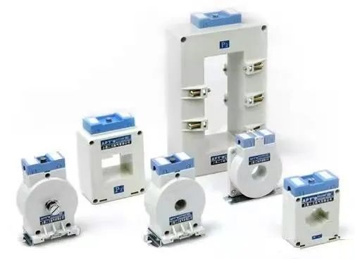
Current transformers and voltage transformers are both referred to as instrument transformers. For measurement or protection systems, it can convert high voltage into low voltage and convert large current into small current. Its main function is to proportionally convert high voltage or high current into standard low voltage (100V) or standard low current (5A or 1A, both referring to rated values), in order to achieve standardization and miniaturization of measuring instruments, protection equipment, and automatic control equipment. At the same time, for the safety of personnel and equipment, transformers can be used to isolate high-voltage systems.
What is the function of a secondary transformer?
Instrument transformer is a type of transformer that utilizes the principle of electromagnetic induction to convert current and voltage. In order to monitor, measure, and protect the system, transformers proportionally transmit power information from the primary circuit to the secondary circuit and provide it to secondary equipment such as measuring instruments and relay protection devices. Due to the sufficient insulation strength between the primary winding and the secondary winding of the transformer, the secondary equipment and personnel can be electrically isolated from the primary high-voltage, and the secondary side of the transformer is grounded at one point, ensuring the safety of equipment and personnel
Advantages and disadvantages of three instrument transformers
Advantages:
They separate high-voltage circuits from measuring equipment and control circuits.
Small rated measuring instruments of 5A and 110-120V can be used to measure high voltage and high current in AC power systems.
Measurement instruments can be standardized by using instrument transformers. Therefore, the cost of measuring instruments is reduced. Damaged measuring equipment can be easily replaced with standardized measuring instruments that are working properly.
Transformers can connect many measuring instruments to the power supply, as long as the total load does not exceed the rated load of the instrument transformer.
Due to the low voltage and current levels in the measurement and protection circuit, the power consumption of the measurement and protection circuit is minimized.
Ammeters and voltmeter are used to measure the large current and voltage in these instrument transformers.
These transformers can be used to operate multiple protective devices, such as relays or indicator lights.
By connecting a long cable to a transformer, the measuring equipment can be placed in a panel far from the high-voltage side. This ensures the safety of the instrument and operator.
Disadvantages:
They can only be used in AC circuits, not DC circuits.
Four transformer types
Transformers are divided into two types: voltage transformers and current transformers.
1) Voltage Transformer (PT)
Convert high voltage to low voltage; The rated voltage of the secondary winding is 100V, which is connected in parallel with the voltage coil and relay protection device of the measuring instrument.
2) Current Transformer (CT)
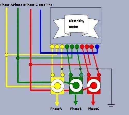
Convert large current into small current; The rated current of the secondary winding is 5A or 1A, and it is connected in series with the current coil and replay protection mechanism of the measuring instrument.

Precautions for the use of five instrument transformers
Precautions for using voltage transformers
1) In addition to selecting a voltage transformer based on the measured voltage, it is also necessary to ensure that the power used by the connected measuring instruments and relays does not exceed the rated capacity of the voltage transformer. Otherwise, the accuracy of the voltage transformer will be affected. The nameplate of the voltage transformer indicates the capacity that matches the accuracy. For example, the JDZ-10 voltage transformer has a capacity of 80VA at level 0.5, 100VA at level 1, and a maximum capacity of 500VA.

(2) Fuses should be installed in the primary and secondary coils of voltage transformers to prevent short circuits. The internal short circuit fault of the voltage transformer and the short circuit fault on the connection line between the voltage transformer and the power grid are both protected by the fuse on the primary side of the voltage transformer. The rated current of the fuse on the primary side of the 10kV voltage transformer is 0.5A. The secondary side of the voltage transformer shall not be short circuited during operation, so a main fuse shall be installed on the main circuit of the secondary side to protect the network below the main fuse from the impact of short circuit faults; In order to prevent short circuits in the instrument voltage circuit, which may affect the operation of the secondary main circuit, a fuse has also been added to the instrument circuit. The total rated current of fuses is usually 3-5A, while the rated current of instrument circuits is usually 1-2A. in the majority of cases
(3) One end of the secondary side of the voltage transformer must be grounded to protect the safety of personnel and equipment. If the secondary coil is not securely grounded, or if the insulation is damaged, high voltage escapes to low voltage, the secondary circuit will be in contact. For employees, this will be a life and death situation. In addition, the insulation of the secondary circuit is insufficient. If there is no grounding point, the insulation will be damaged, and the voltage transformer will be more severely damaged.
(4) When checking the voltage transformer, check whether the porcelain bottle is clean and whether there are any fractures, faults, or discharge phenomena. Whether the oil level of the oil immersed voltage transformer is normal and whether there is serious oil leakage or leakage phenomenon; When each phase is grounded, listen to the voltage transformer for grounding monitoring to see if the sound is normal and if there is any odor.
Precautions for using current transformers
1) According to the principle of series connection, the primary winding of the current transformer should be connected in series with the tested circuit, while the secondary winding should be connected in series with all instrument loads.

2) Otherwise, if an appropriate conversion ratio is not selected based on the measured current, the inaccuracy will increase. At the same time, one end of the secondary side must be grounded to prevent the high voltage on the main side from entering the low voltage side of the secondary once the insulation is damaged, resulting in injury to personnel and equipment.
3) The secondary side should not be open circuited, because once open circuited, the primary side current I1 will all become magnetizing current, causing a sharp increase in m and E2, leading to saturation magnetization of the iron core, severe heating, and even coil burnout;, This increases the error. The secondary side of the current transformer is used in series with the current coil (such as measuring devices and relays) during normal operation. Current coils, such as those in measuring instruments and relays, have very low impedance, and the secondary side is similar to a short circuit. In addition, an open circuit on the secondary side can cause the voltage on the secondary side to reach hundreds of volts, which can cause electric shock if handled. Therefore, the short-circuit switch is installed on the secondary side of the current transformer to prevent its disconnection. Once the secondary side is open, immediately remove the circuit load and handle the power outage. After everything is thrown away, it can be reused.
4) All circuits are installed in generators, transformers, outgoing lines, busbar segmented circuit breakers, busbar circuit breakers, bypass circuit breakers, and other circuits to meet the requirements of measuring instruments, relay protection, circuit breaker fault diagnosis, and fault filtering. The secondary winding is used for 2 to 8 current transformers.
5) The protective current transformer should be installed as far away as possible from the primary protection device to eliminate non protected areas. For example, if allowed on site, two sets of current transformers should be placed on both sides of the circuit breaker to put it in a cross protection state. Range
6) In order to avoid busbar problems caused by flashover of pillar type current transformer bushings, current transformers are usually installed at the output of circuit breakers or transformers.
- Prev:None
- Next:What is eFPGA?
-
Whatsapp

